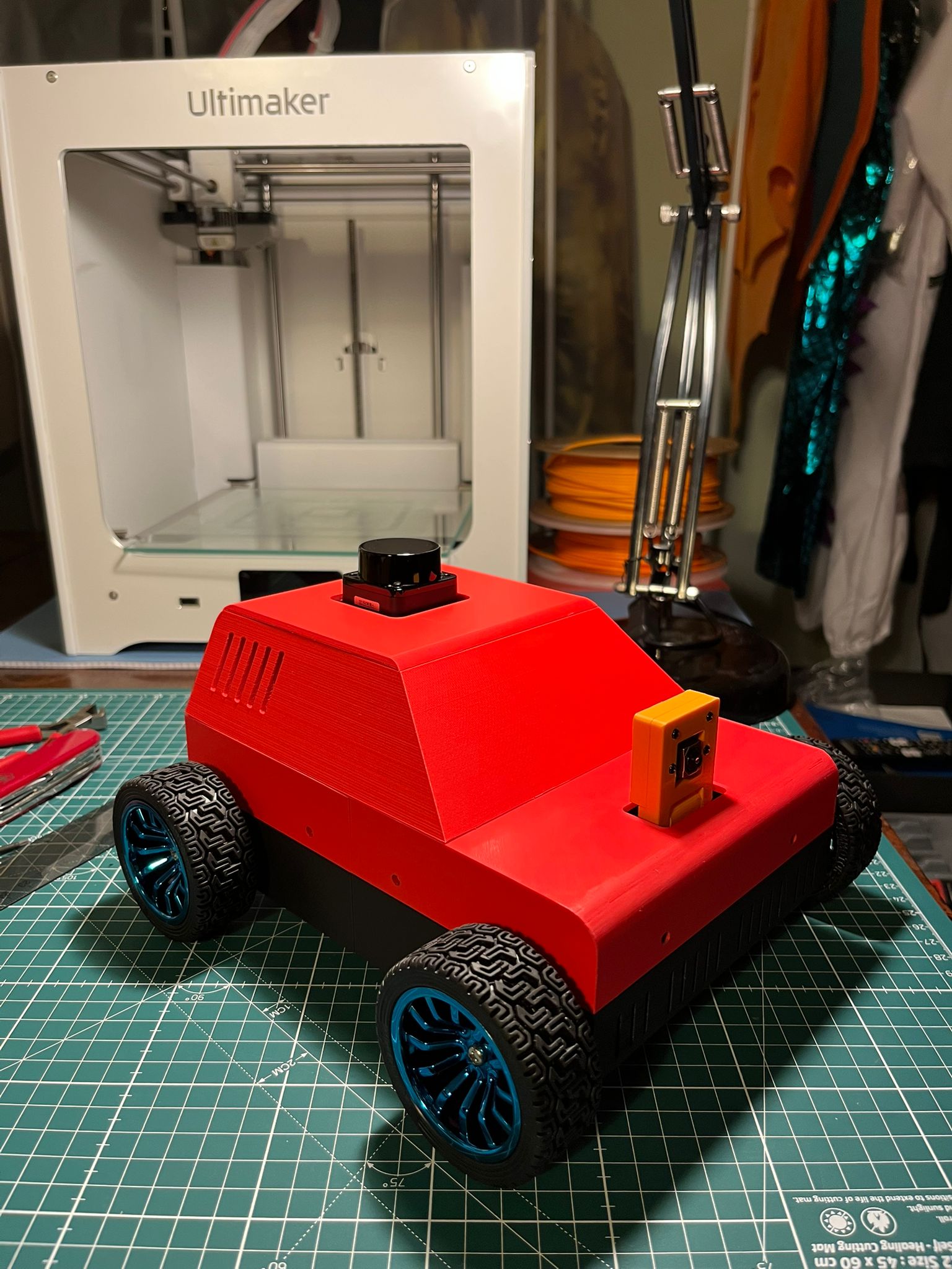
A Custom ROS2 Mapping (SLAM) & Navigation (Nav2) Robot Which Operates In Real Life And In Simulation.
Project Goals:
Build a custom, real, diff-drive robot running on ROS (Jazzy) that can be launched into ‘map mode’ (where it can be teleoperated whilst performing slam mapping) and then launched into ‘nav mode’ where it uses Nav2 to navigate the environment using the map it made.
The robot will use an IMU sensor, wheel encoders, a lidar, and a camera (the camera so the user can map an indoor environment without having to physically follow the robot around).
Motor control and IMU sensor will be handled by a Raspberry Pi Pico. Compute, lidar, and the main ROS nodes will be run by an onboard Raspberry Pi 5.
Design the ROS program to be a fully distributed system allowing simulation work to be done on a dev machine during development (e.g. Gazebo, RVIZ) and also for the dev machine to be used for visualisation when mapping with the real robot.
Physical and software design to be robust enough to handle multiple environments including different surfaces, and differing complexity of indoor environments.
Steps Required:
Decide on the functions the robot needs to perform and the features it will therefore need.
Based on the requirements, conduct research into and make decisions on the components needed.
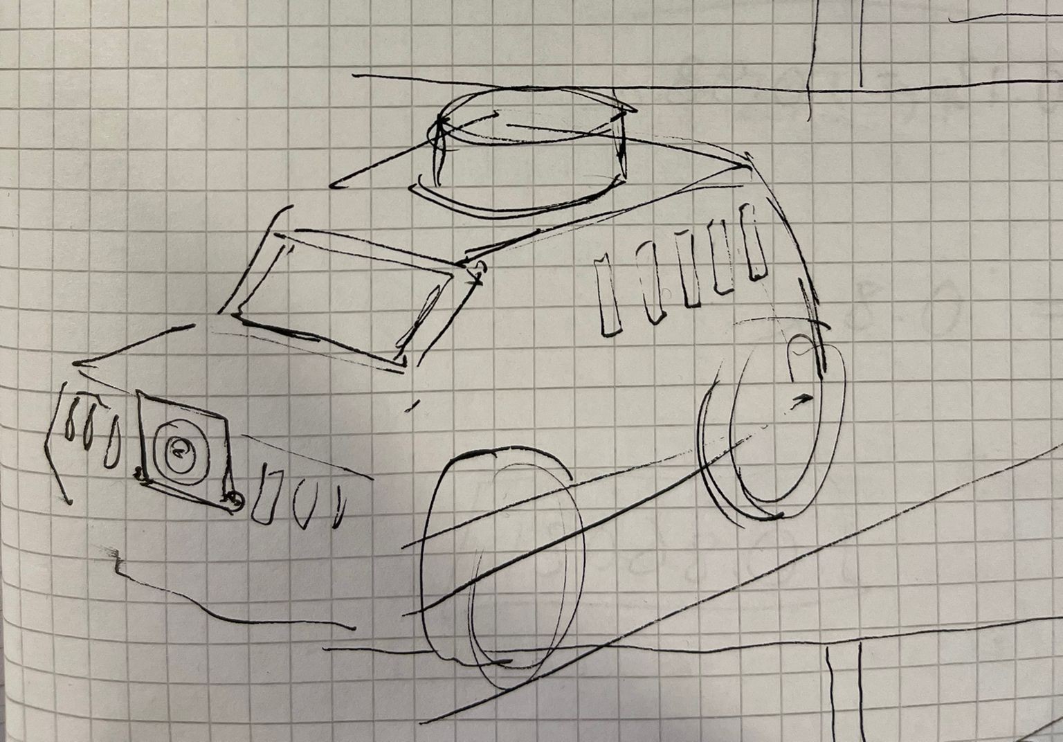
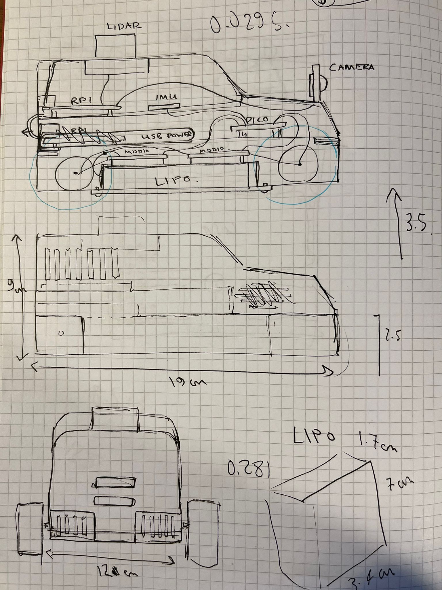
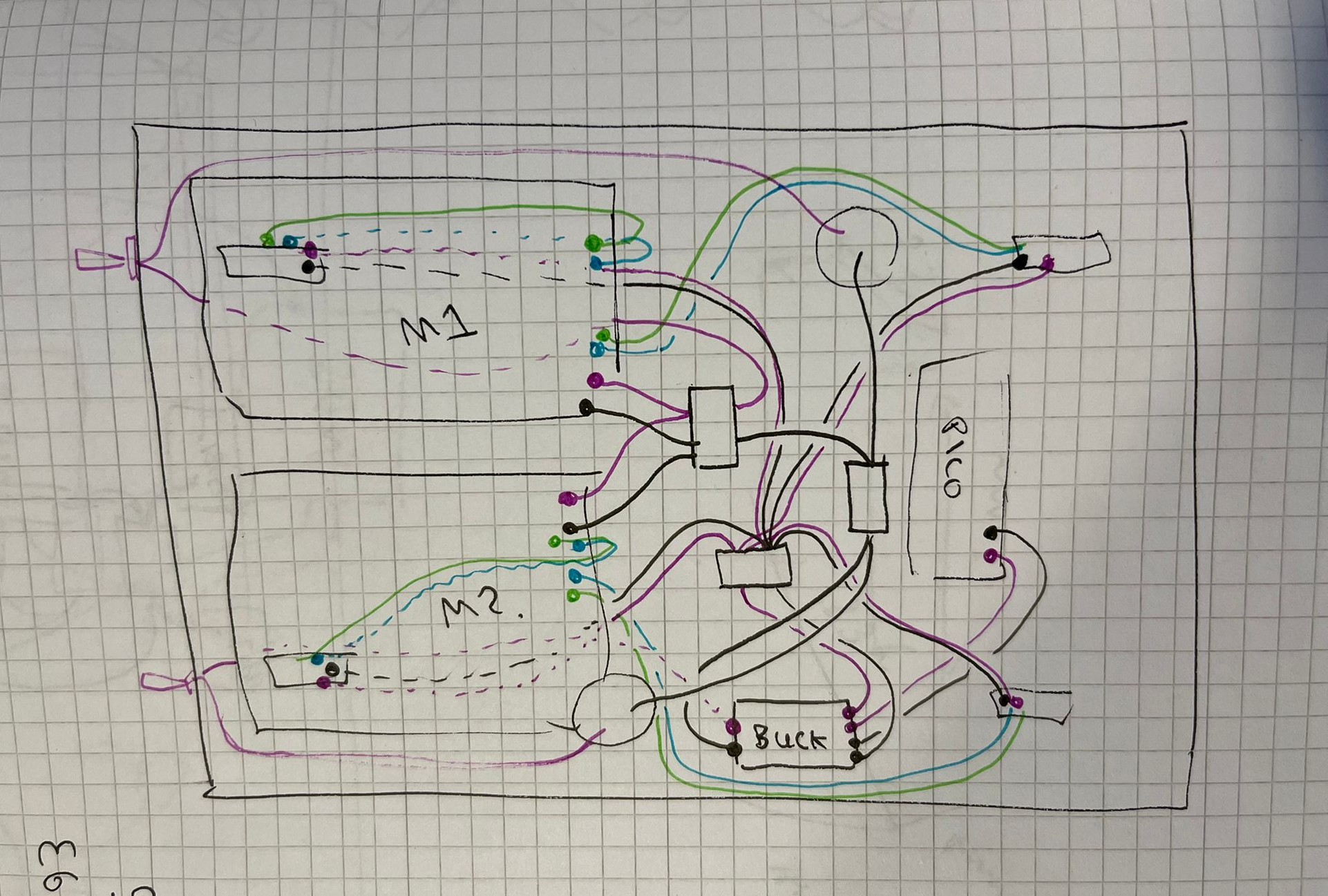
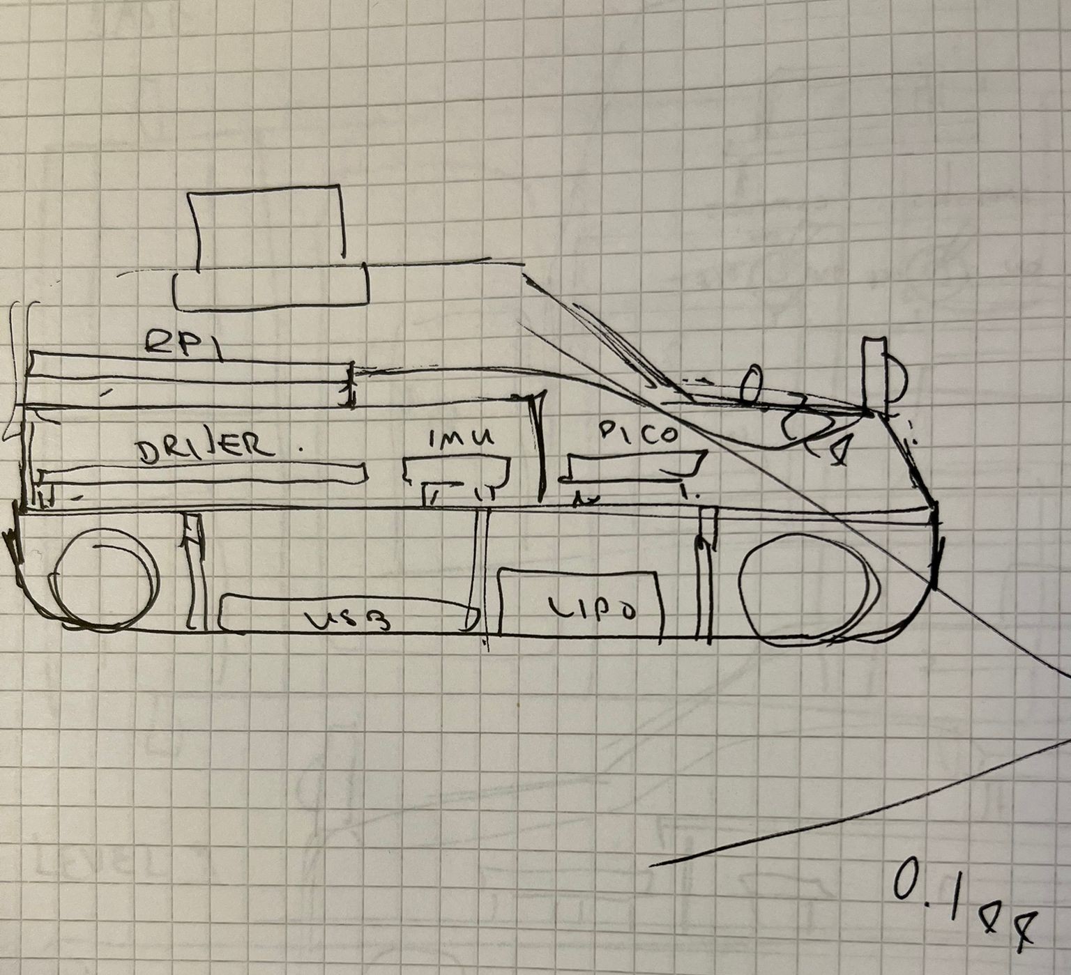
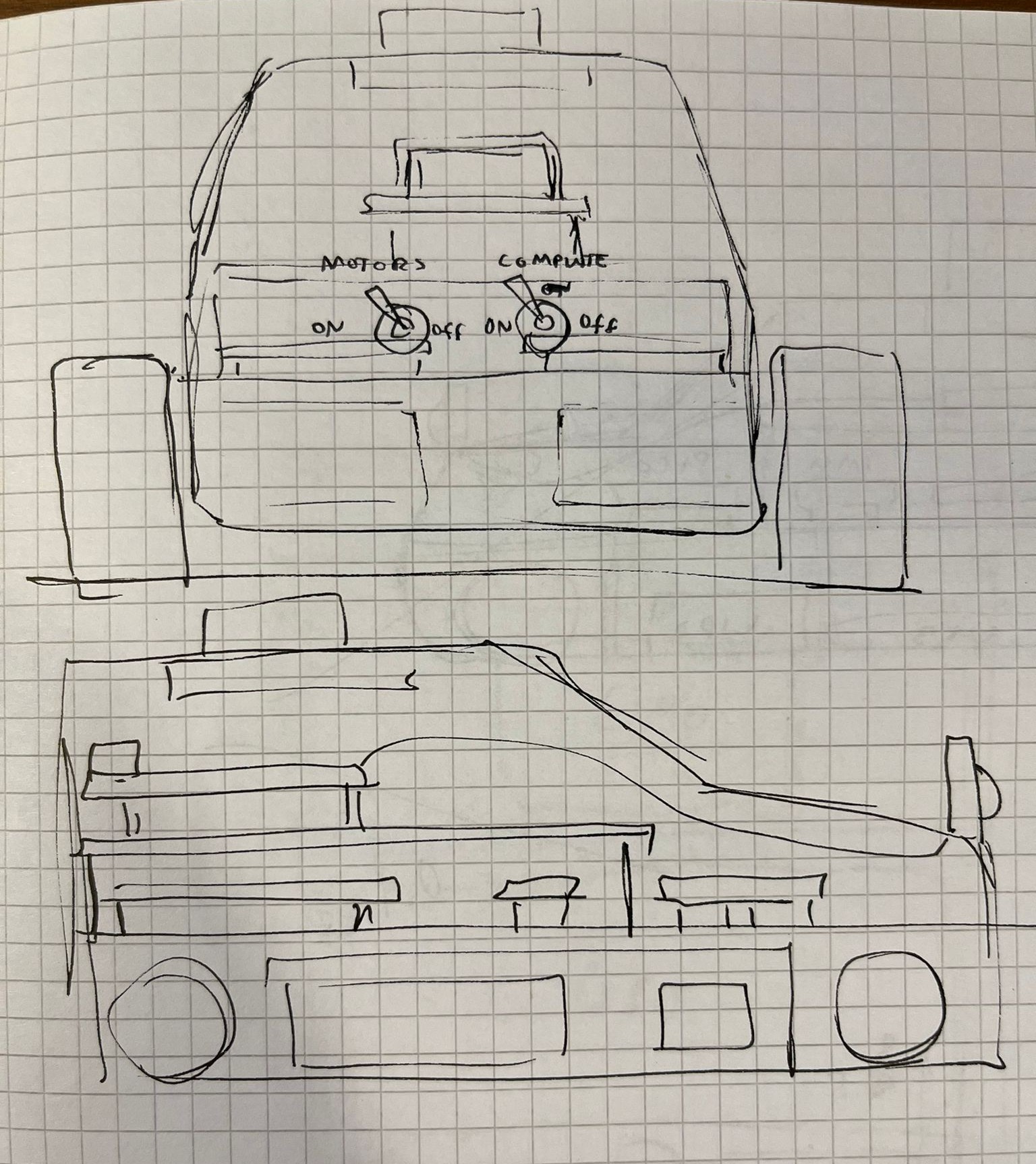
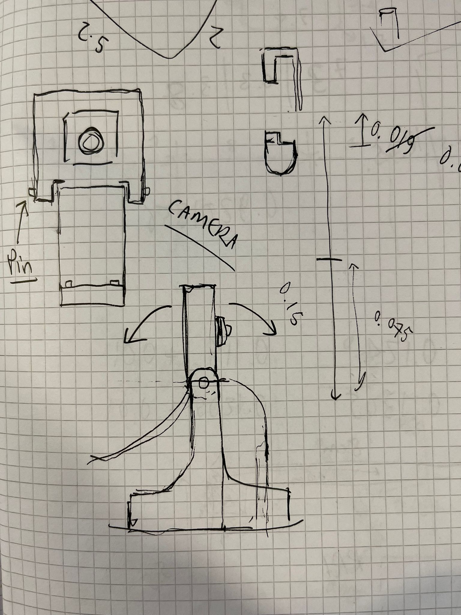
Prepare a basic ‘on paper’ design of how the robot will need to look, what sort of size it will need to be, and also a ‘roughed out’ design of the internals to allow for neat and modular packaging of components and wiring.
Conduct a detailed design of the physical robot on CAD (plus a simplified version for simulation purposes).
Build phase 1 of the ROS program (on the Dev machine) which will allow the robot to be launched into simulation and to perform all its necessary functions (SLAM, Navigation, Localization etc) in simulation.
Procure all necessary components, print all parts to be printed, and build the physical robot. Iron out any hardware bugs along the way, make any changes to componentry due to unexpected issues.
Build and thoroughly test the motor driver (which will live on the Pico). Ensure accurate PID control under varying load conditions and surfaces. Ensure no brown out issues on the Pico due to current spikes. Ensure no other hardware related issues. Test the IMU sensor data is both accurate and reliable. Ensure at this stage that a Micro ROS agent can successfully latch to the Pico.
Build phase 2 of the ROS program (on the Dev machine) which incorporates the real physical robot including ros2_control, the associated hardware interfaces, and any third-party drivers (e.g. for lidar and camera). This also included some launch files for the dev machine for viewing the real robot when it is running a program on the embedded Raspberry Pi.
Set up the Raspberry Pi 5 with Ubuntu Terminal, install ROS, clone the slambot ROS package to it and ensure all dependencies installed. Make sure Micro Ros agent installed and working, and any third-party drivers including for the Lidar and the Raspberry Pi Cam. Test lidar and camera first to ensure both are functional. Test the various ‘real robot launch files’ on the RaspberryPi (via SSH) and ensure everything is running as expected (including that robot can boot into various modes dictated by a toggle switch).
Perform thorough testing of the REAL robot’s kinematics behaviour. For example, robot travels 2 metres in real life, is this reflected in the robot’s pose on ROS?
Perform thorough testing of slam mapping, apply any necessary slam tuning changes. Perform thorough testing of Navigation behaviour, including any necessary tuning of Nav2 params.
Clean up the GitHub Repo to make it theoretically ‘production ready’ including detailed .md guides for initial setup (particularly on the embedded devices) and a list of materials and the necessary CAD files.
Project Demo Video:
Detailed Project Breakdown
Step 1: Functions & Features
The goal of this project was to take everything I’ve learned about SLAM and Nav2 and incorporate it into a real physical robot, as well as building a decent ROS2 simulation program. The robot therefore needed to be able to be teleoperated, and to perform slam mapping whilst being teleoperated. The robot then needed to be able to launch into Nav2 and load a map up it had previous created and to successfully navigate that environment.
In order to achieve this, I decided the robot needed to have the following:
Four decent motors (with quadrature encoders)
Motor drivers capable of dealing with high current spikes.
A front facing camera (to allow for mapping without having to physically follow the robot around)
A 360-degree 2D lidar
A 9-axis IMU sensor
Two power supplies (one for motors, and one for compute).
An onboard microcontroller
An onboard computer
A decent step-down voltage converter
Three toggle switches – one to power on motors, one to power on compute, and one to select between map-mode and nav-mode.
Step 2: Decision on Components
For the computer, the obvious choice was a Raspberry Pi 5 (8GB) which would have enough compute and memory to handle SLAM mapping whilst being cheap, small and having lots of ‘plug and play’ components such as the camera module.
As I decided to use a Raspberry Pi 5 for the onboard SBC, I decided to use a Raspberry Pi Pico for the microcontroller. Not only are these nice and small (for packaging purposes) the fact they can run Micro-ROS and are designed to work in harmony with the Pi 5 made me feel this was the right choice (though it wasn’t without its challenges!)
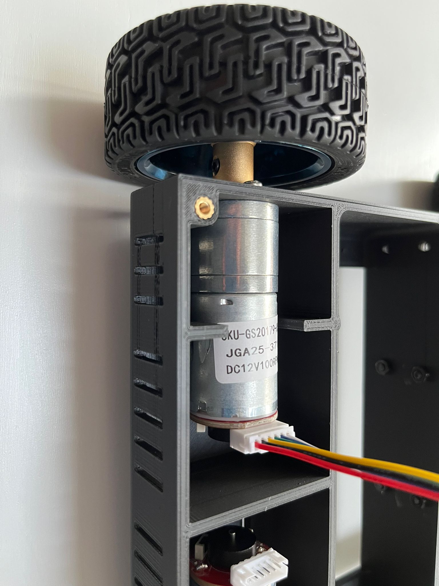
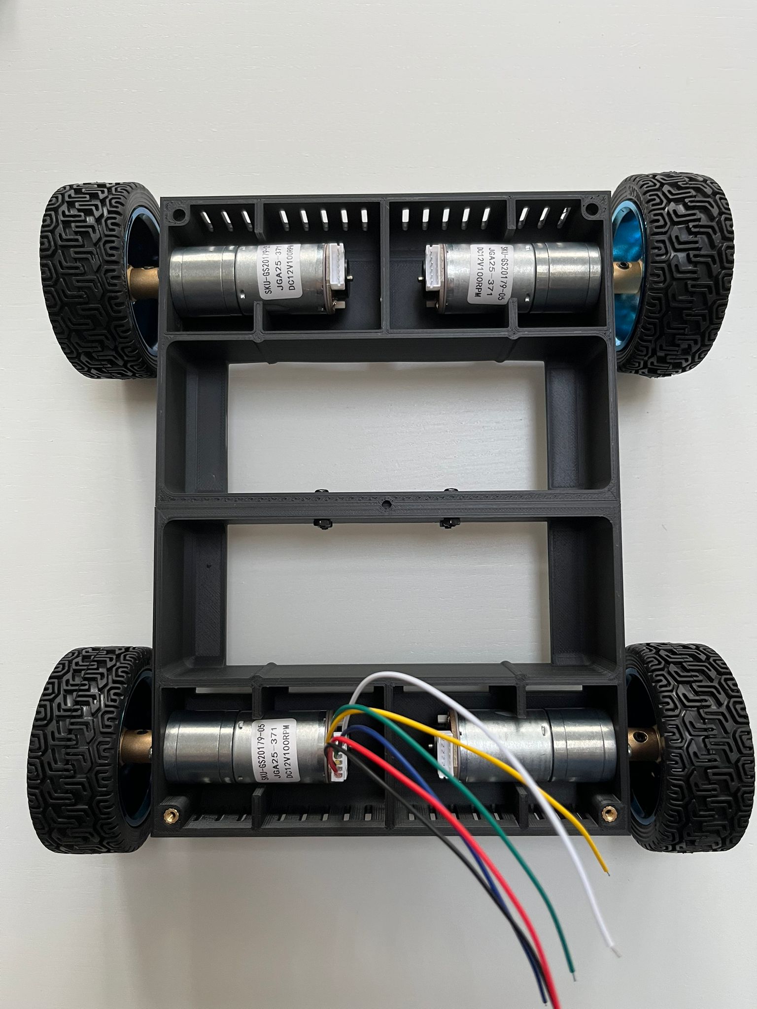
For the motors after some research I opted for JGA25-371 100rpm DC motors with quadrature encoders. These are an unbranded Chinese made motor, but had very positive reviews, and could be bought as a set which included some high-quality wheels. The size and shape of the motors also lent themselves to allowing me to do some very neat packaging with them on the physical robot. 100rpm was chosen as the motors needed a fair bit of torque, and I wanted to motors to be smooth and slow for mapping purposes.
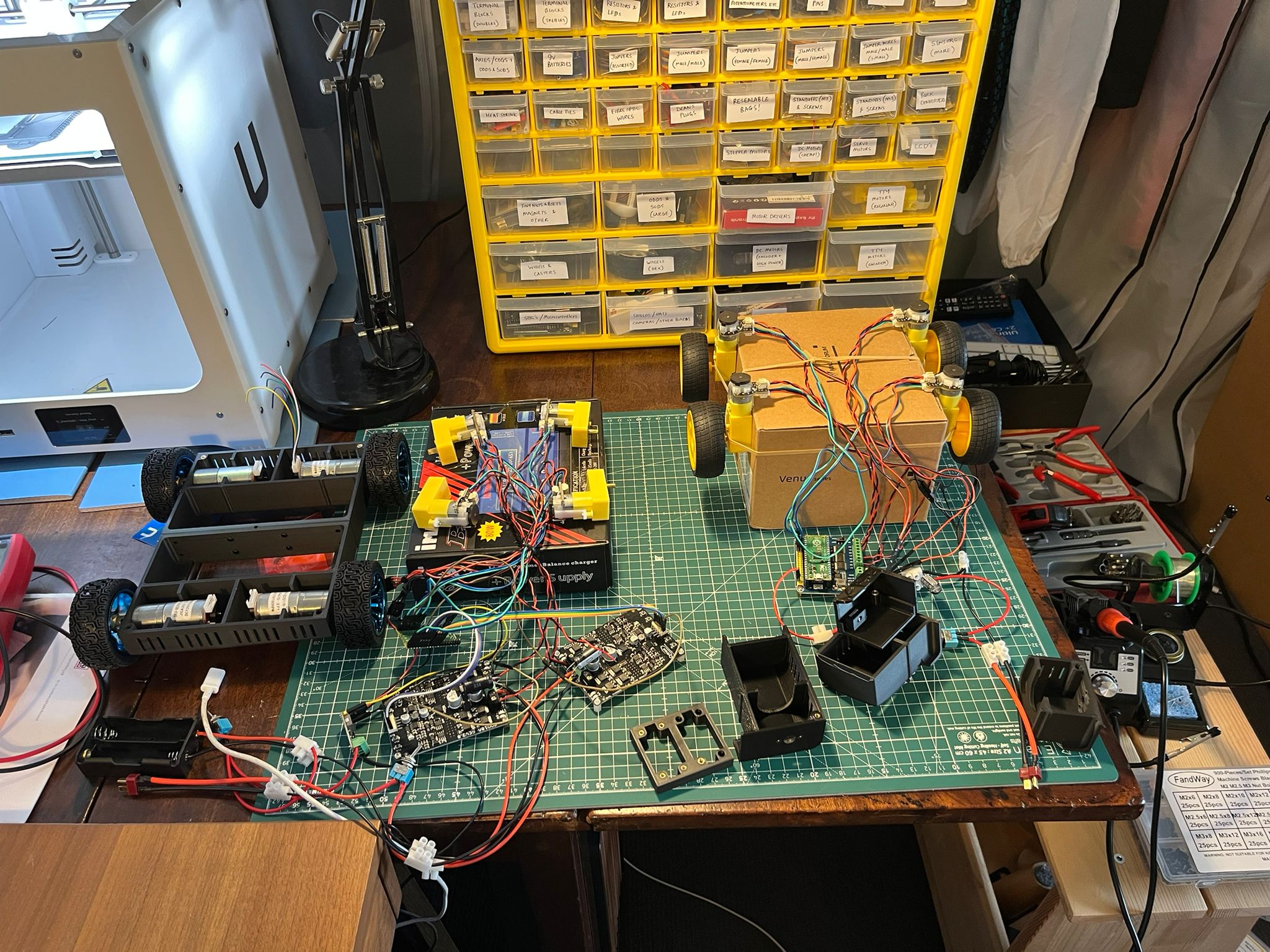
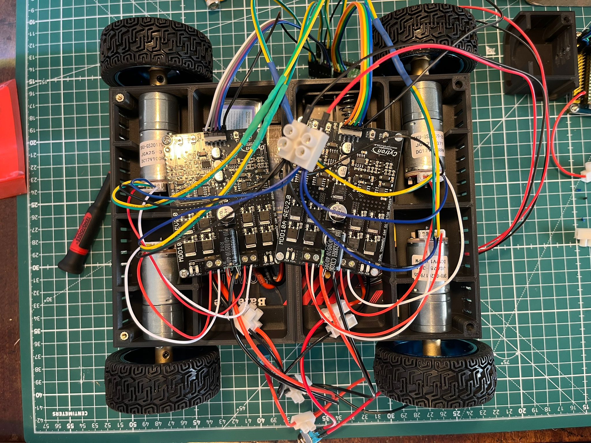
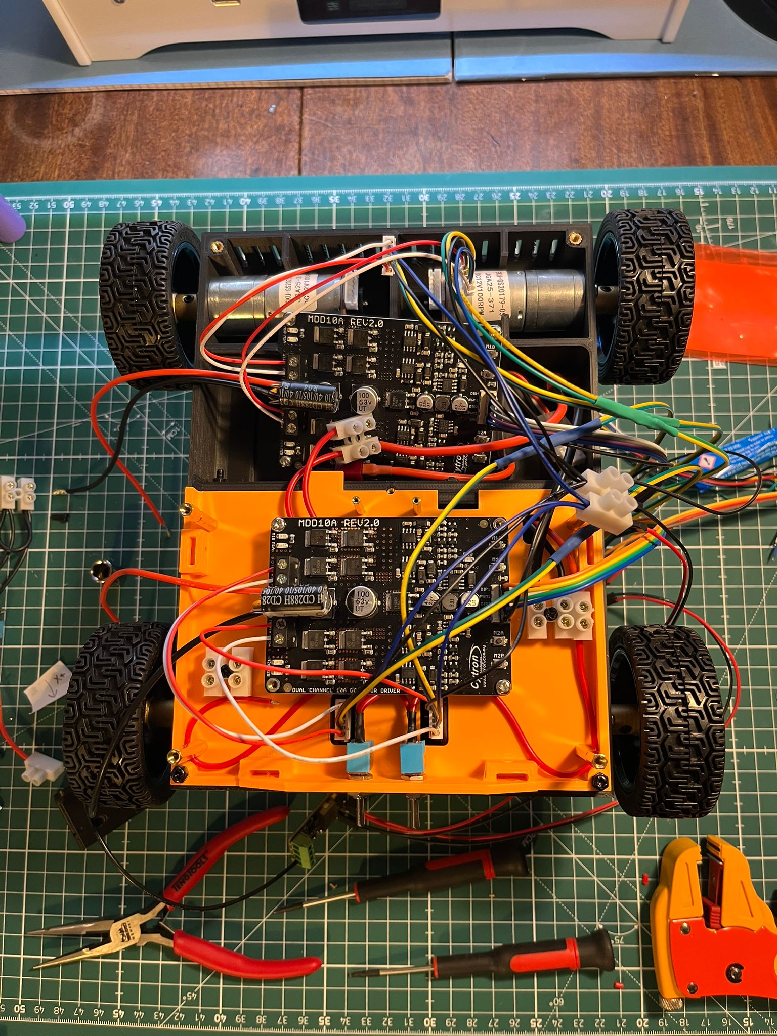
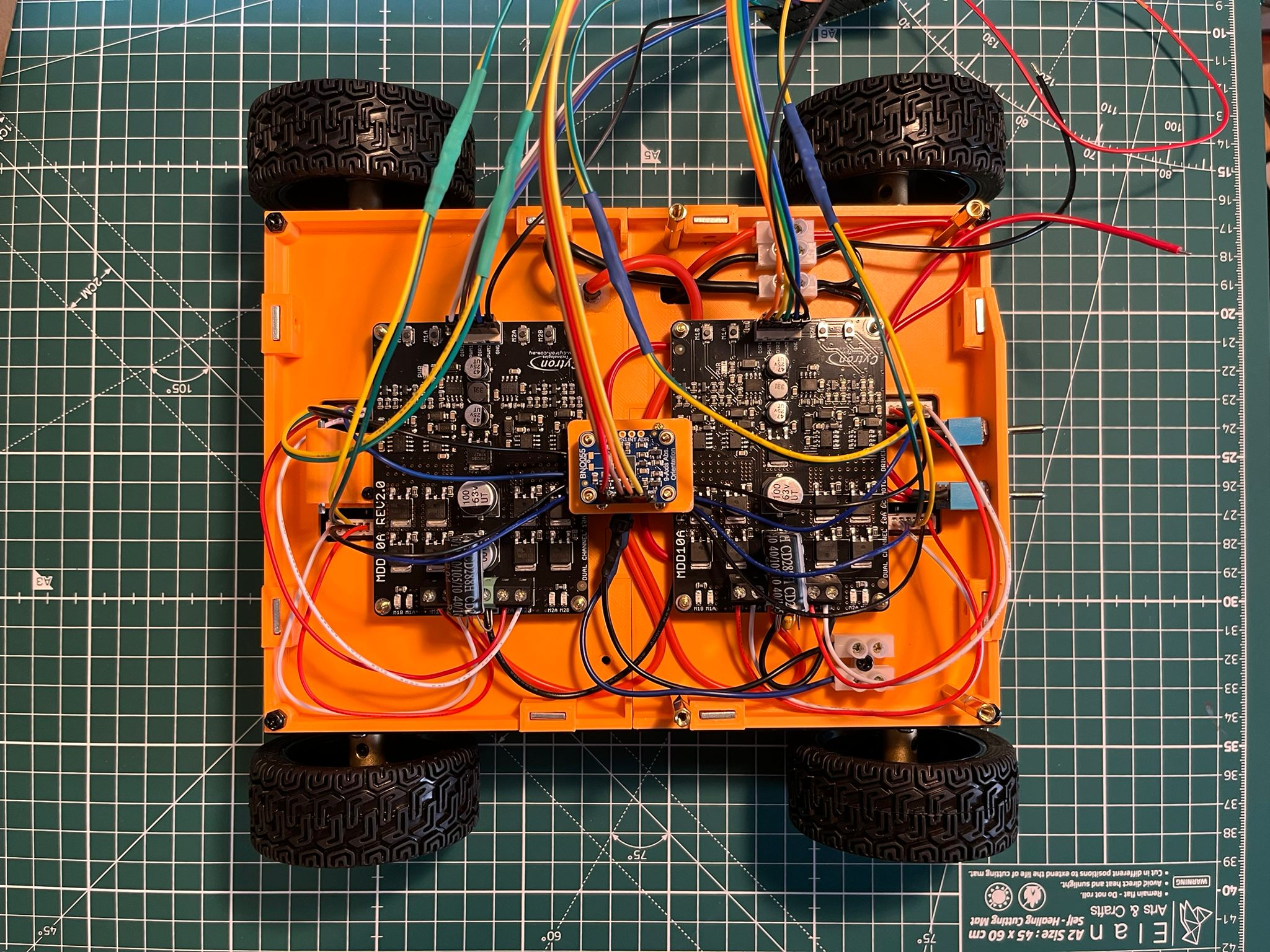
For the motor drivers, after some bench tests, it was immediately clear I would need something quite beefy to avoid brown-outs on the Pico. After some research I opted for two Cytron MDD10A twin-channel drivers. They are a bit bulky, but on the bench tests, they completely eliminated any brownouts (even without additional capacitors – which I did still add anyway to be safe).
For the lidar I chose the OKDO LD-06 lidar as it is a fairly common model with some decent existing ROS-ready drivers and is small and cost effective. It also has a mount designed for the RaspberryPi which allowed for some nice neat packaging on the physical robot.
For the IMU sensor I decided to opt for a BNO055 9-axis IMU sensor as it had all the requirements in a very small package size and was very cheap.
For the power supplies I opted for a high-discharge (50c) 3-cell Lipo Battery for the motors offering over 12v and 2400mAh. For the compute I opted for a 2-cell Lipo battery offering 8v and 2400mAh.
For the voltage step-down converted I opted for a Waveshare DC5-36-TO-DC3V3-5 unit as it was small, had good reviews and appeared capable of providing the necessary current to the compute modules (though – this was later changed to a module with a higher max Amps rating).
Bench testing various motor drivers and motors:
Step 3: Basic ‘On Paper’ Designs
Before jumping into any detailed CAD designs I needed to get a feel for the general shape, size and internal packaging of the robot. This I did with many sketches on paper some of which are below:
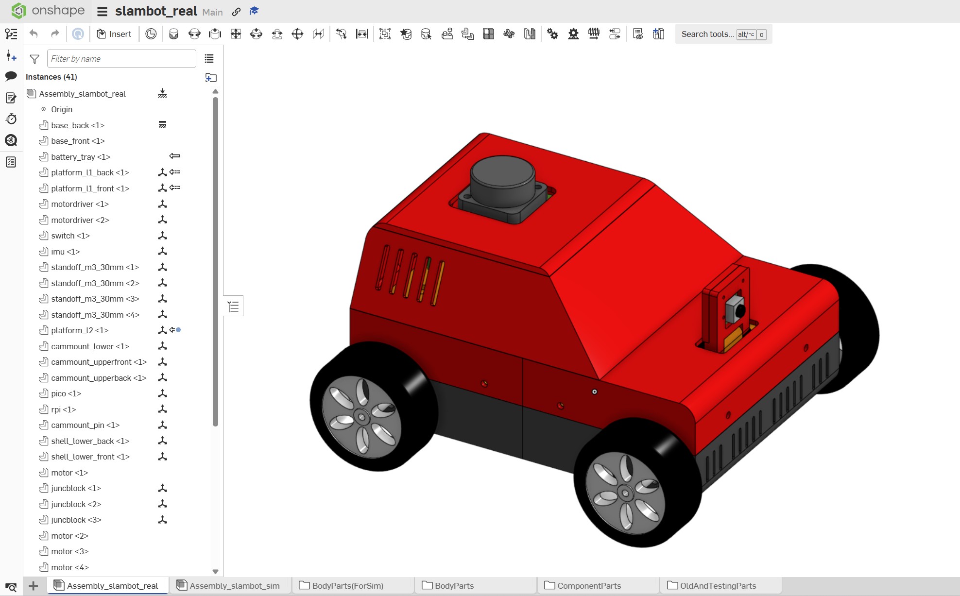
Step 4: Detailed CAD Designs
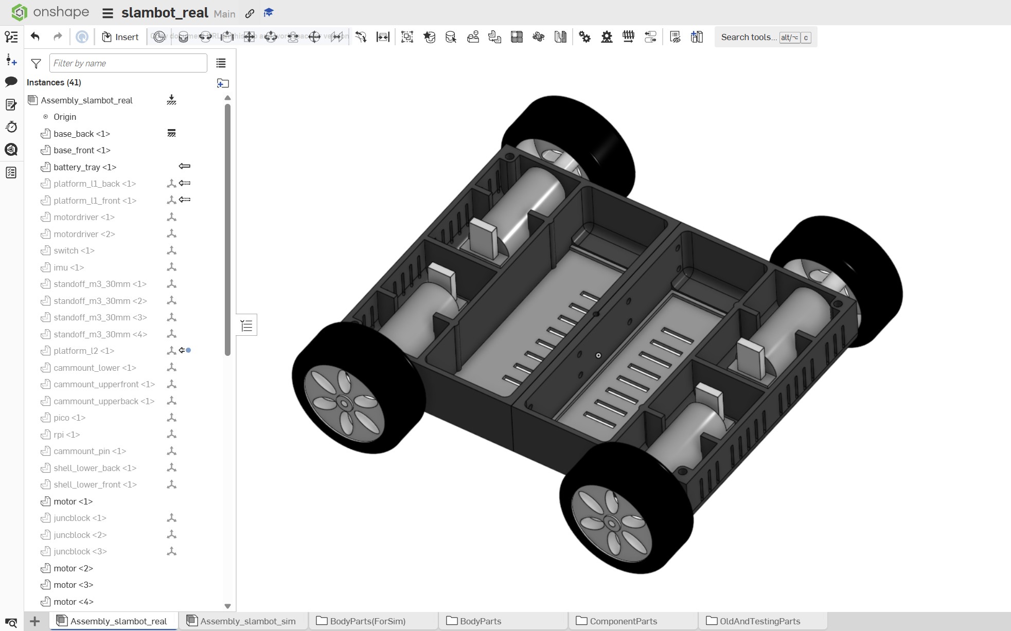
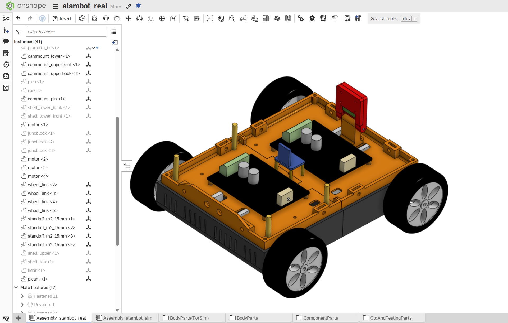
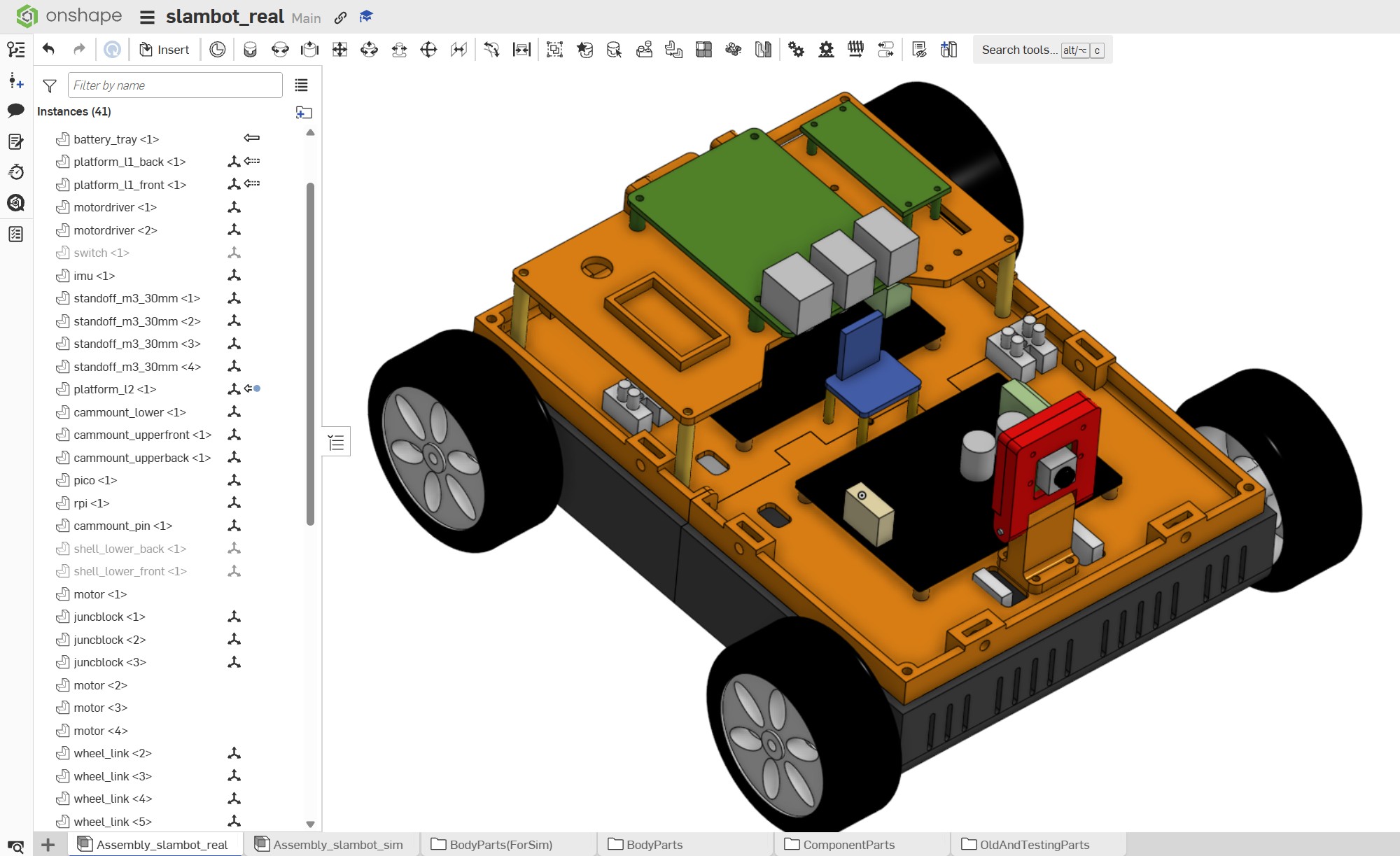
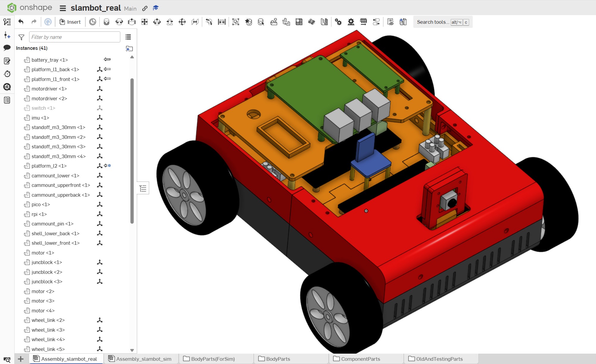
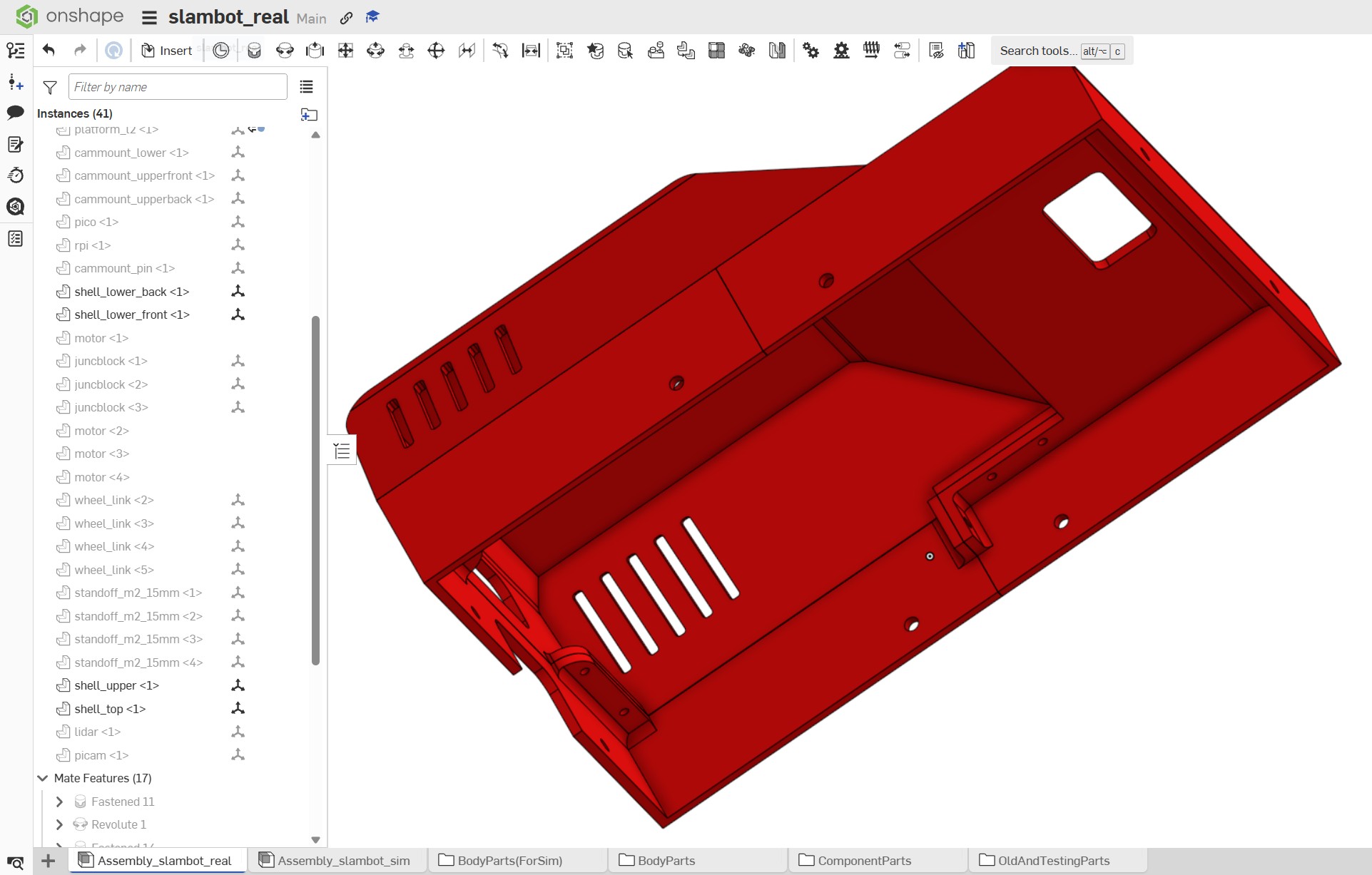
A key constraint on the design of the robot was the fact most of the parts would be 3D printed, and the print-bed size on my printer is relatively small. I therefore had to design certain parts in pieces which would then be bolted together. I also wanted the robot to be designed in such a way that it can be very easily disassembled (for example, if a motor breaks, I could simply lift the platform off which contained all the wiring and compute and sensors etc with very little effort).
Step 5: Phase 1 of the ROS program (Simulation)
Next up, now I had a CAD model (and bear in mind I also created a significantly simplified version of it for Gazebo and RVIZ purposes) was to get the ROS program built for sim.
The main issues I faced were:
Getting the sim setup working was Gazebo running VERY slow (I later learned to decimate my Gazebo models and use extremely simple collision model for my robot)
Getting slam_toolbox working properly on sim and it turned out to be an issue with the gazebo lidar sensor which required a gz_frame_id inserted which was never mentioned in the documentation!
Getting Nav2 working properly and a lot of time was spent tuning parameters (often going backwards a long time before any progress was made) to get the robot to behave acceptably based on the indoor environment I made.
Video of Slambot In Simulation:
Video of my workflow for using 'onshape_to_robot':
Step 6: Build The Physical Robot
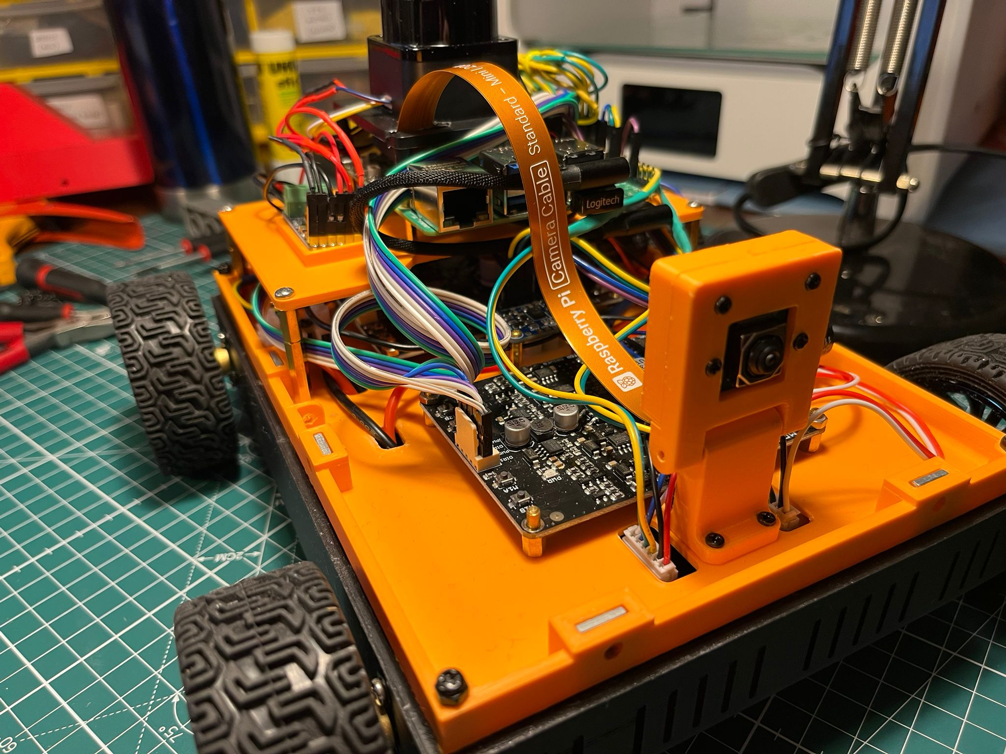
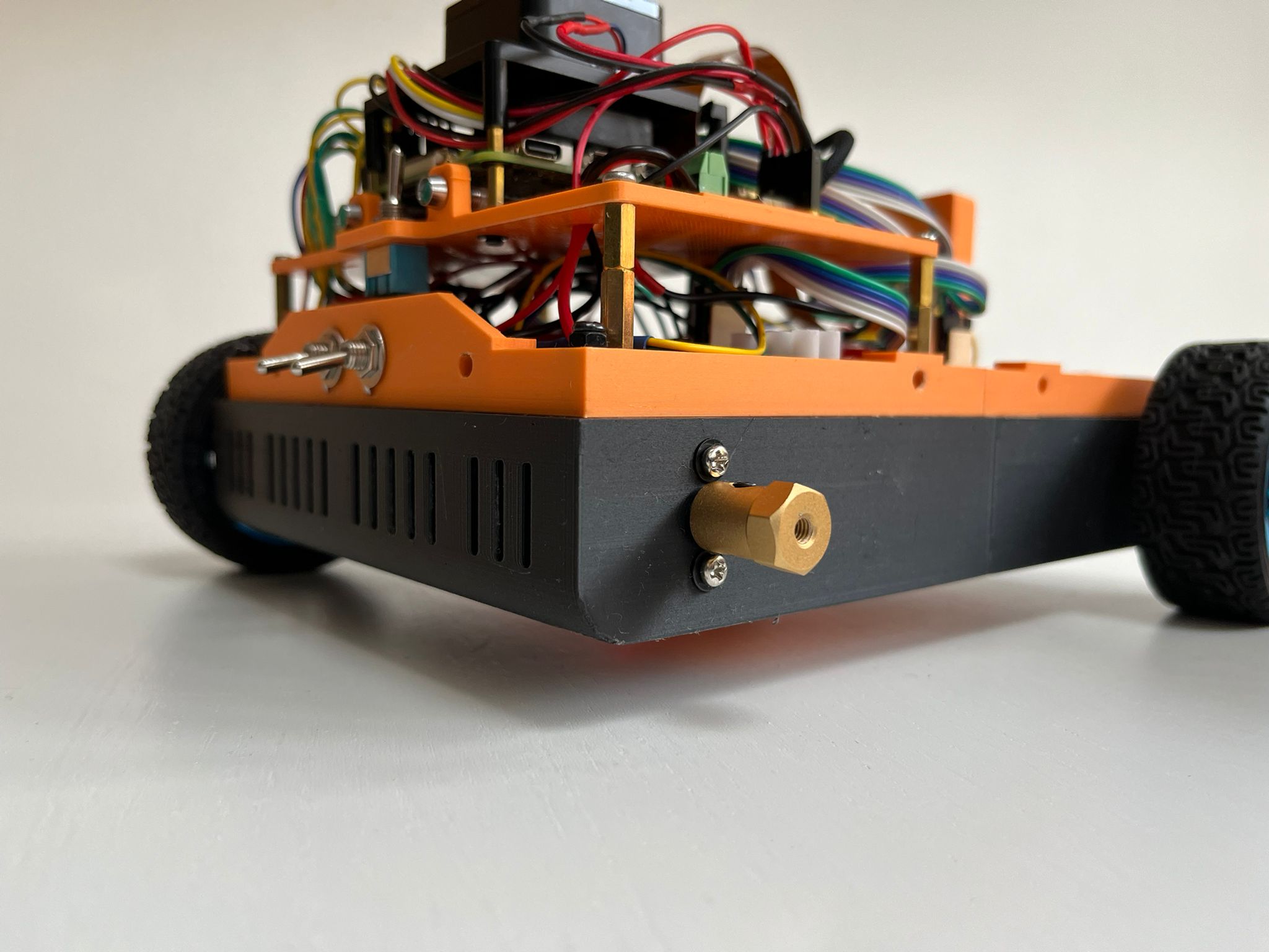
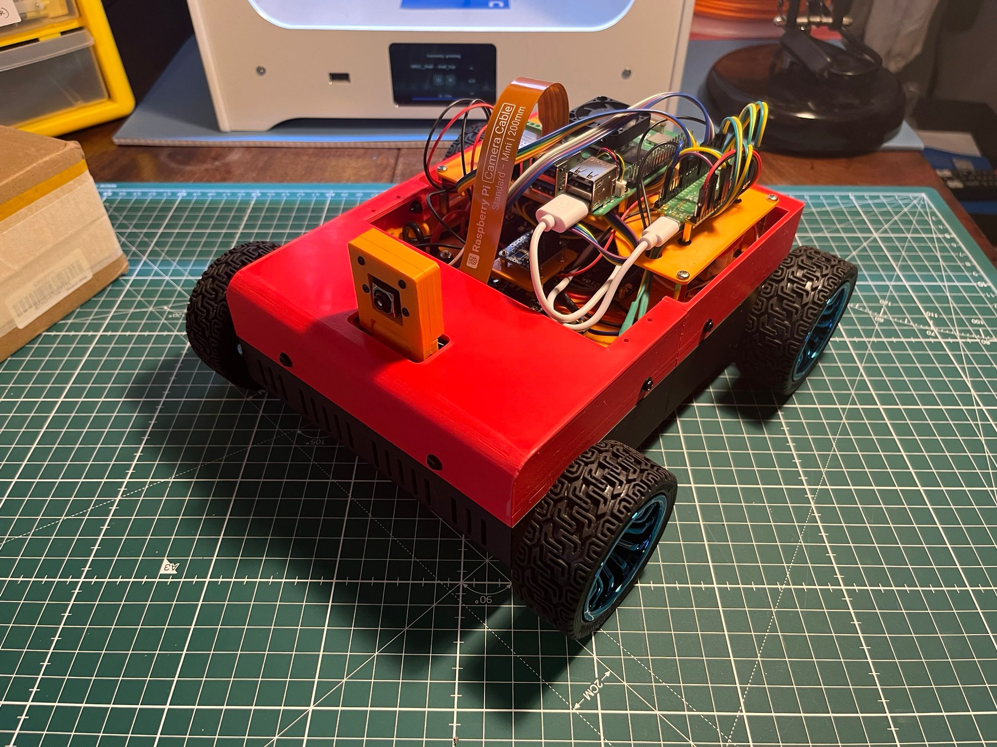
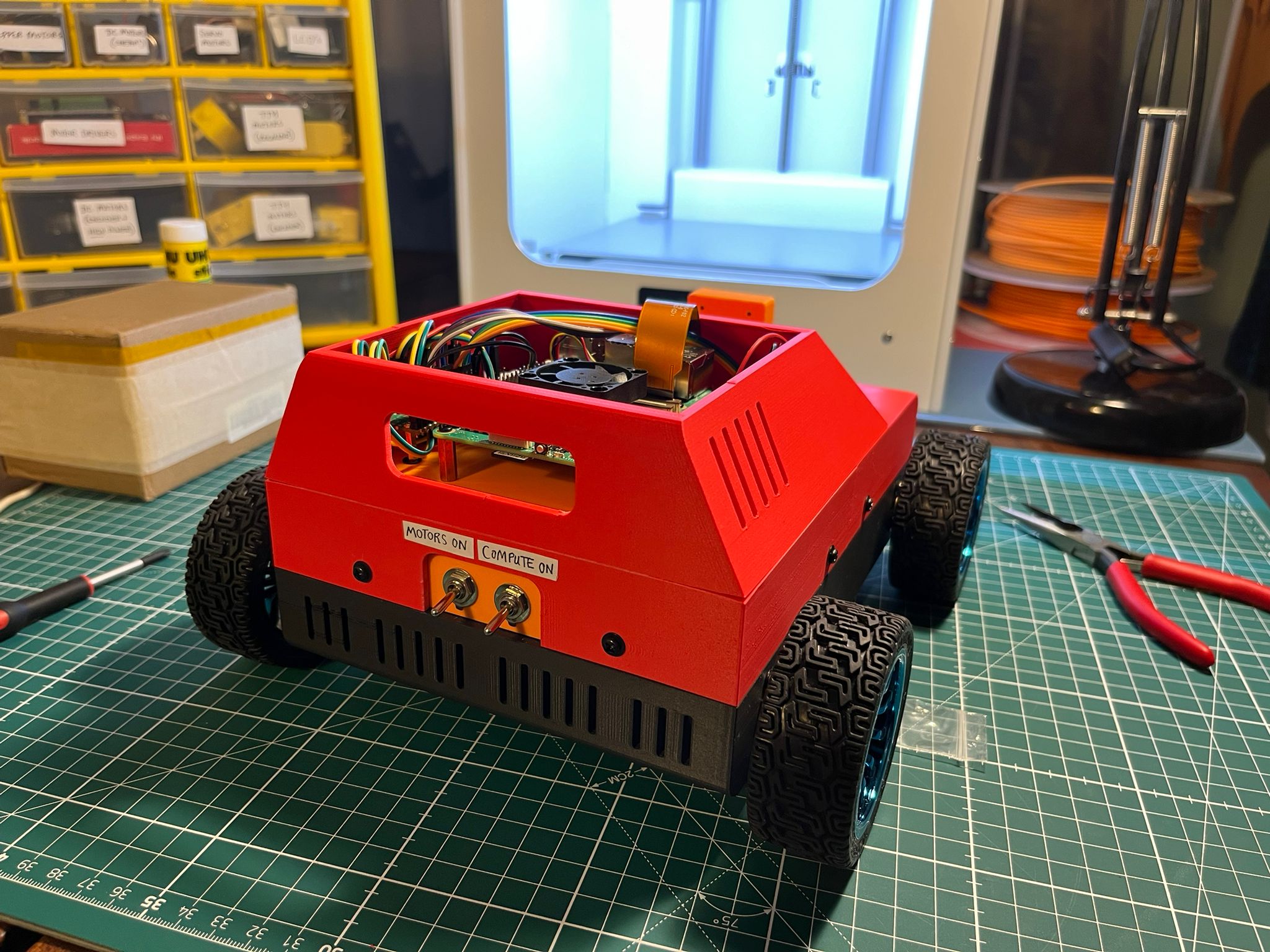
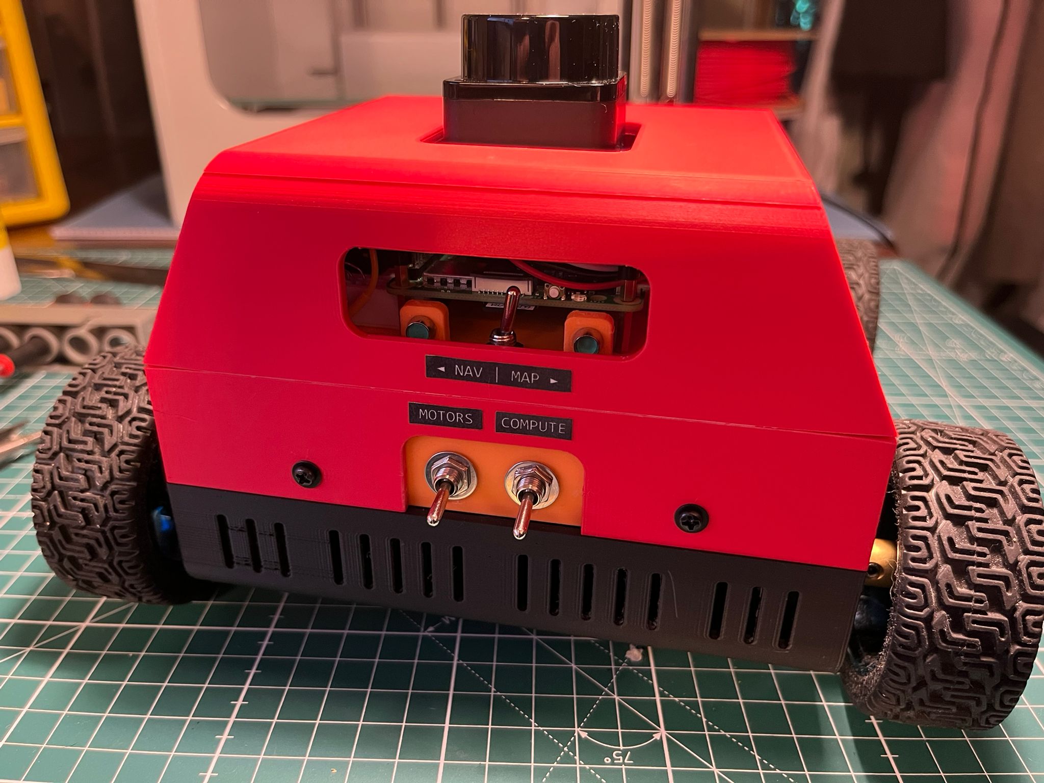
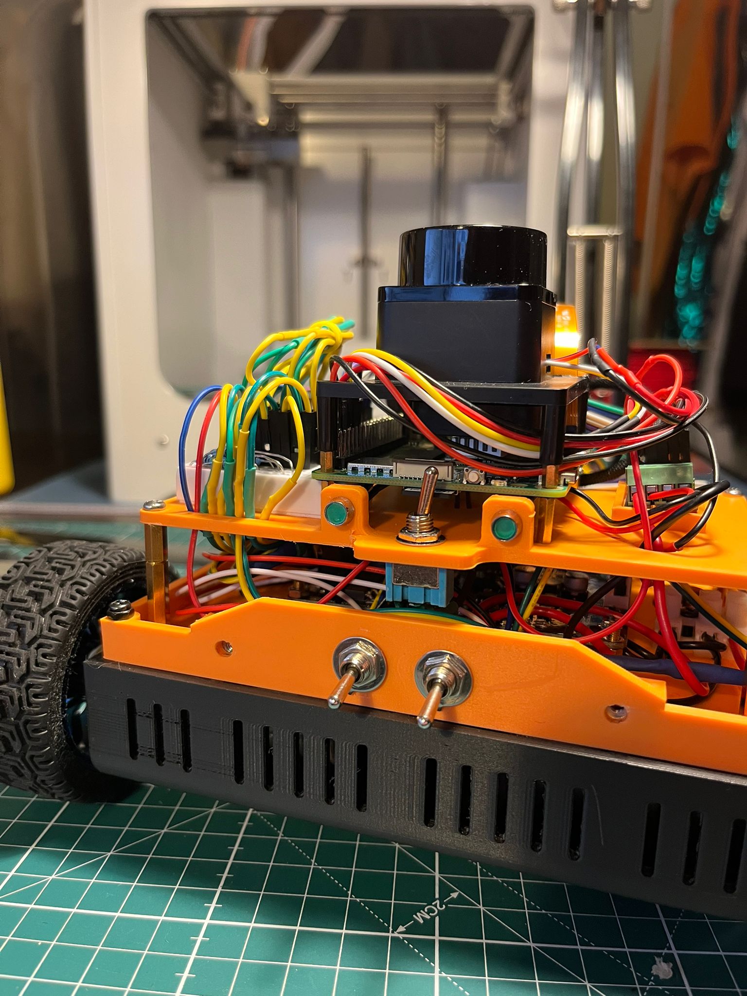
This step involved a lot of 3D printing and a lot of soldering, but it was incredibly fun and was brilliant to see slambot come alive in real physical form. I was also really pleased with some of the features I designed including:
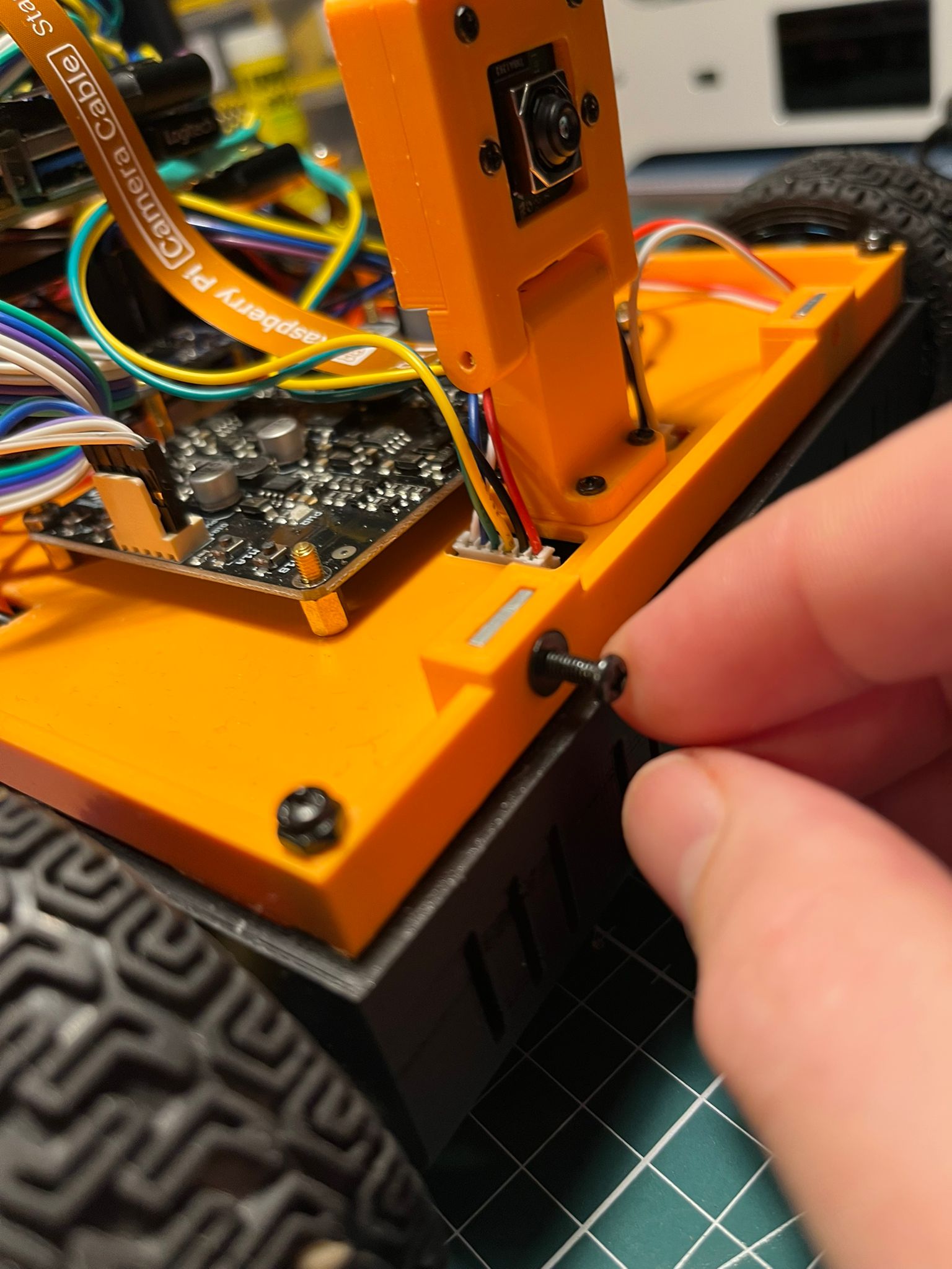
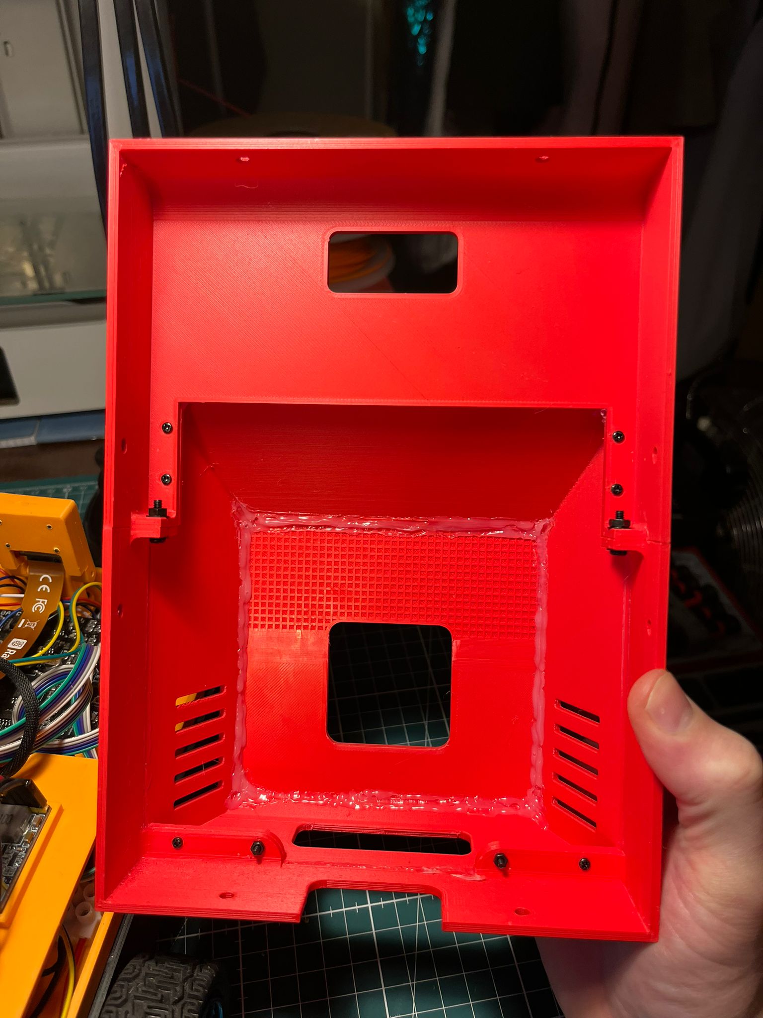
Using the square bolts in the orange platform to allow the red outer shell to be easily bolted down to the base whilst still giving the robot a completely flush finish!
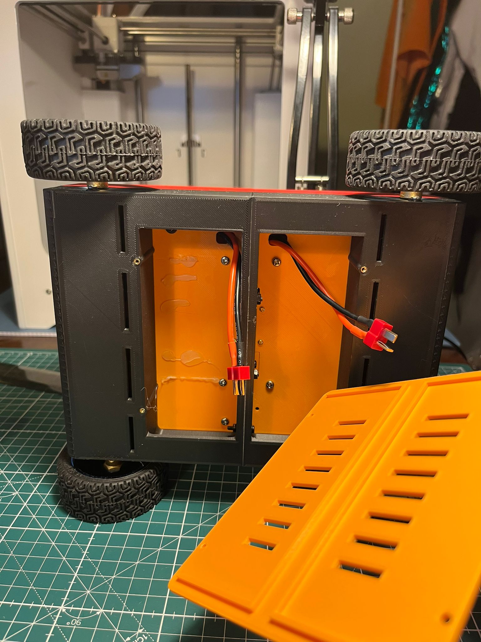
The main orange platform that holds all the wiring to be completely modular and removable without having to unwire or remove anything if access is needed for the motors!
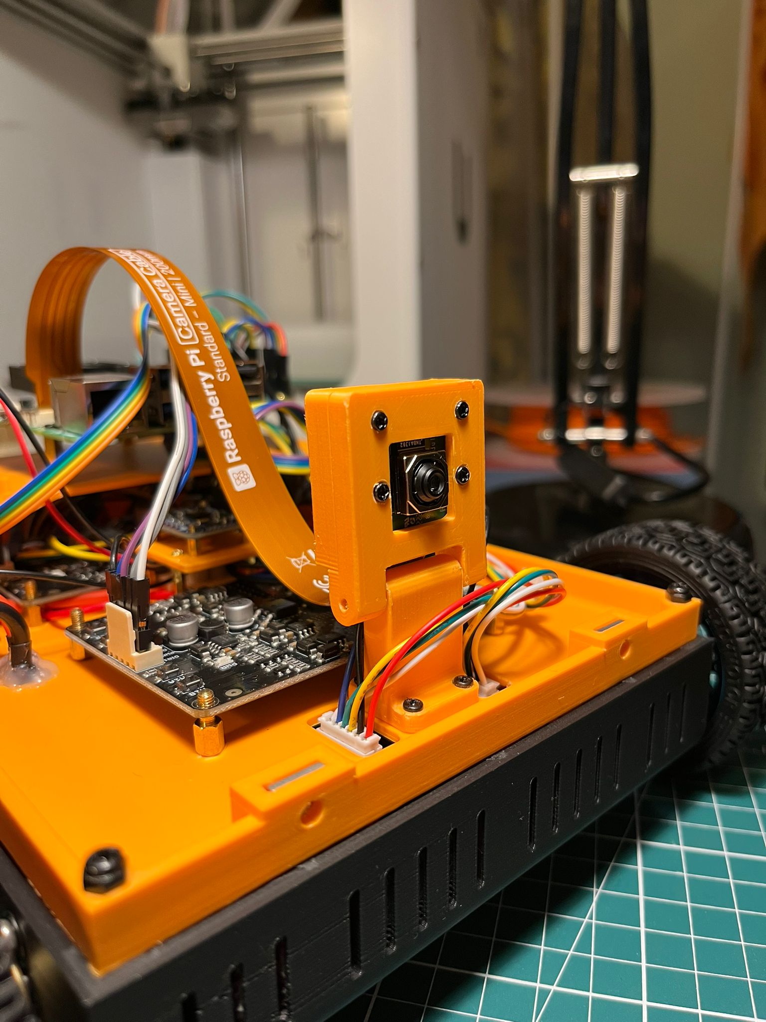
The camera mount with swivel which allows for the camera to be directed exactly where you need it!
Step 7: Motor and IMU Driver for Pico (Inc. Micro ROS)
This was probably the most daunting bit for me as I’ve never actually used a Pico as my MicroController before (preferring previously to use Arduino) and I had never used Micro ROS. The motor driver itself with the PID control was complex, but doable provided I took it step by step, and made sure to test thoroughly before moving onto any new code. The IMU sensor was fairly simple to implement.
I did go down a 7 day long rabbit-hole at this stage though, as for some reason my PID control and motors worked perfectly in forward, but in reverse I got completely bizzare behaviour where the ticks coming through the encoders would be reading the same for each motors, but I could visually see they were not spinning at the same speeds. This turned out to be solved by using a state machine for the encoder ticks to handle the situation where messages from the A line were being ever so slightly delayed compared to the B line when in reverse which effectively tricked the driver into initially thinking the motors were spinning forward. It’s quite hard to explain the issue and how I solved it in writing… but the key thing is, I eventually (after many hours and a few tantrums) solved it!
Step 8: Phase 2 of the ROS program (Real)
Next up was to incorporate into the ROS program the real robot. This included getting ros2_control setup and working, along with the associated hardware interfaces. I also needed to write some top-level launch files specific to launching the real robot (these would of course be run only from the Raspberry Pi). I also at this stage needed to locate and install the ros2 lidar driver I would be using.
Lastly, I implemented some dev machine launch files which would launch GUI viewing capabilities on the dev machine for when the real robot was running.
Testing the PID control:
Step 9: Set up the Raspberry Pi 5
Setting up the Raspberry Pi was a fairly lengthy process. It involved the following steps (full details in the 'docs' section on the GitHub Repo):
Flash and install Ubuntu Terminal
Set up SSH access and automatic connection to my home Wifi
Install ROS Jazzy Barebones
Install LibCamera and get PiCam working properly
Set up directories for the ROS program, and clone package into the Pi
Install various dependencies
Install and test Lidar Driver and Camera ROS Nodes
Install and test the MicroROS Agent
Connect via serial to the Pico and test that Pico latches on boot
Test various launch scripts and make edits to the config.txt file
Write a boot script and service that is linked to the 'mode-select toggle switch on the robot'
Step 10: Testing REAL robot’s kinematics behaviour
Here I performed a range of real-world tests to ensure that what the robot physically did, was reflected in the pose on the ROS program. The tests included:
Driving robot forward 2 metres, and checking to see if the transforms reflected this distances - applying changes where needed to wheel-radius
Driving robot backward 2 metres, and checking to see if the transforms reflected this distances - applying changes where needed to wheel-radius
Performing 360 degree turn (left and right) and checking transforms and pose to ensure ROS program was also reflecting a 360 degree turn
Step 11: Testing SLAM Mapping & Navigation Behaviour
Here I performed lengthy SLAM mapping and Nav2 tests in the real worls and in a range of indoor environments (including on different surfaces). Significant parameter tuning was required (particularly for Nav2) to ensure the robot behaved acceptably well in the real world environment. The ROS program was actually reworked slightly here to allow for a separate set of SLAM and Nav2 parameters to be loaded depending on if the robot was in simulation or in real.
Step 12: Clean up GitHub Repo to make it 'production ready'
My final task was to clean up the GitHub Repo and make it production ready. Despite the fact this is not a production robot, I felt it was good practice to do this. The cleanup involve making sure the Repo was structured in such a way to provide the ROS packages, but also detailed documentation, the firmware, the CAD files and walkthrough guides such that anyone could clone the Repo, follow the instructions and build a slambot of their own!